Fatigue

The Importance of Balancing and Weighing a Bulk Materials Handling Machine

A bucketwheel reclaimer is a balanced machine that needs weighing

During the commissioning process for a balanced mobile Bulk Materials Handling Machine (BMHM) such as a bucketwheel reclaimer, stacker, bucketwheel stacker reclaimer or shiploader, an important step is to balance and weigh the machine. Although it may be tempting to forego this vital step due to schedule demands and the impending commencement of operations, it is imperative that proper balancing and weighing be carried out to ensure the safe and reliable operation of the machine for many years to come.

Validates the Design Intent

Balancing and weighing of a new machine on site allows for comparisons to be made between the measured and design values. Any discrepancies regarding the luffing structure balance and total weight of the machine may require further investigation and rectification prior to commencement of operation. This practical validation step is an important hold point before handover. The Australian and international standards for mobile BMHM do not allow the as-constructed weight to be more than a 5% variation to the design value, in which case the design checks and calculations must be repeated.

Avoiding False Confidence

If only balancing or weighing is undertaken, and not both, this does not provide the machine’s owner a complete picture of their new investment. As an example, weighing alone might indicate the machine’s mass matches the design value. But this might give the project team a false sense of confidence, because without also undertaking appropriate balance and centre of gravity checks on-site the machine’s stability cannot be verified and it might be improperly balanced, which may not be obvious from weighing alone.

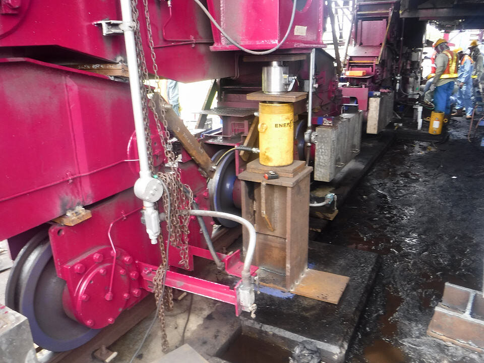
Preparing to undertake weighing of a stacker reclaimer

Achieve the Fatigue Service Life

The stability, balance and centre of gravity is critical for a machine that undertakes luffing and/or slewing motions, such as a bucketwheel reclaimer, stacker or shiploader. If the machine is not properly balanced, the fatigue stresses caused by each luffing and/or slewing motion can be amplified and the slew bearing load distributions may also be outside its design load envelope. As such, an incorrectly balanced machine will have a shortened slew bearing service life and premature onset of fatigue cracking.

 
Hydraulic jacks used to weigh a stacker reclaimer
 

Confirm Wheel Loads on Rail

The loads imposed on the wheels and rails for a bulk materials handling machine depend not only on the machine’s overall weight but also its balance and overall centre of gravity. An overweight or incorrectly balanced machine will have excessive wheel loads which can lead to wear issues for the wheels and rails. It can also mean that the long travel drive power may not be adequate for the machine to operate efficiently. These increased loads can also have significant consequences for the wharf or rail foundations, which were designed and built for a specific design wheel load spectrum.

The Best Methodology

The correct counterweight is critical for the machine balance

The best method for balancing and weighing will depend on the design and configuration of the particular machine, therefore using an incorrect methodology can give erroneous or inconclusive weight and balance results. There are many factors to consider which add together to create complexity. Taking measurements with the boom horizontal is sufficient for some machines but not for others. If the conclusion is that the machine is overweight or improperly balanced, what is the path forward? Adding or removing counterweight can have significant implications elsewhere on the machine that need to be fully understood.

In recognition of the importance of weighing and balancing, the requirement of Australian Standard AS4324.1 (2017) states that:

After a machine has been constructed, the mass and centre of gravity of the as-built machine shall be accurately determined
— Clause 5.9 of AS4324.1 (2017)

The team at LEC are experienced in preparing suitable procedures to validate the luffing structure balance and weighing of the entire machine in accordance with the requirements of AS4324.1 as well as other international standards such as ISO 5049-1 and FEM Section II (2 131 / 2 132).

Logan from LEC recording measurements from a machine weighing on-site

Click here to contact LEC and discuss the best methodology for weighing and balancing your particular bulk materials handling machine.

Structural Design Review of a Tandem Rotary Tippler

FEA analysis of a rotary tippler

LEC has recently completed an independent third-party structural design review of a new tandem rotary tippler and its associated positioner and wheel grippers. The new tippler was procured in order to increase the annual export throughput of an iron ore port.

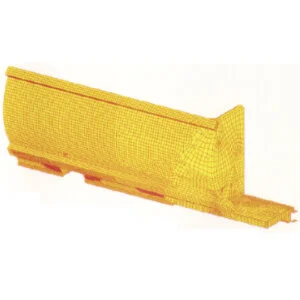
Finite element model of the tippler and positioner structures

Finite element model of the tippler and positioner structures

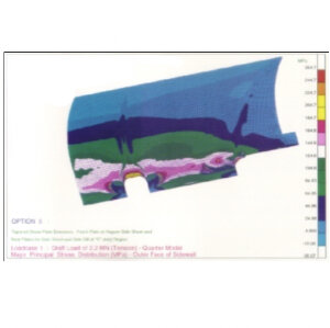
Typical fatigue stress range calculations

Typical fatigue stress range calculations

Detailed structural modelling and analysis was carried out independently using advanced Finite Element Analysis (FEA). Due to the cyclical motion of the tippler, design checks were focused on the fatigue service life assessment. Stress fluctuation due to the rotating motion of the tippler was calculated by analysing the tippler in several angular operating positions.

The independent design review was predominantly carried out in parallel with the Original Equipment Manufacturer’s (OEM) design process to meet the stringent project schedule. Design anomalies and structural non-conformance with the relevant design codes were promptly communicated to the OEM, thus allowing any required modification to the design to be implemented early in the design phase. This reduces the risk of potential costly production delays due to design issues and the associated on-site remedial work as well as the potential for commercial and/or legal disputes.

Tippler during transport

LEC also carried out a design review of the vertical lifting arrangement and transport saddles for land and sea transportation of the tippler cage structure, from the OEM’s fabrication yard to the owner’s site.

Fatigue Cracking of Rail Wagons

Typical heavy haul rail wagons

Consistent fatigue cracks were observed in a number of coal wagons, which had resulted in loss of revenue for the rail operator. Structural modification of the wagon body structure was required to prevent the crack from re-appearing. The main challenge on this project was to develop an effective solution while minimising the increase in wagon tare mass. Any increase in the ore wagon weight would reduce their payload and the associated revenue.

Fatigue life assessment procedure

As part of the design process, a finite element model of the wagon was created. The model incorporated sufficient details to reasonably predict the location and magnitude of stress concentrations and hence locations where fatigue cracking may initiate. Fatigue analysis was carried out in accordance with the recommendations given by the Association of American Railroads (AAR), Fatigue Design of New Freight Cars. The results from this analysis were in close agreement with the locations of the existing cracks.

Based on this assessment, a local structural strengthening solution was developed to effectively reduce the fatigue stress. The geometry of the local strengthening was optimised to minimise the weight and for ease of installation. The proposed structural modifications (<1% of the wagon tare mass) have since been successfully implemented and have extended the service life of the wagons by at least 15 years.

LEC’s Finite Element Analysis (FEA) Capabilities

Advanced FEA analysis by LEC

Why use FEA ?

Structures in the resource and heavy industrial sectors are often geometrically complex and cannot be readily simplified to a traditional beam/frame structural analysis approach. Advanced Finite Element Analysis (FEA) techniques facilitate a more accurate representation of plated structures and thick casting / forging components using 2-D and 3-D elements, respectively.

Examples of FEA by LEC

What FEA software does LEC use ?

LEC use MSC.FEA finite element software, which is a combination of MSC.Patran (finite element modeling pre- and post-processing software) and MSC.Nastran (finite element analysis solver). Nastran is a finite element analysis program that was originally developed for NASA, in the late 1960’s, in the United States. LEC personnel have been using MSC.Nastran software since 1992.

What FEA is not

FEA is not a silver bullet for complex structural problems. The old adage of “garbage in garbage out” is very applicable to FEA computer analyses. Proper selection of solution parameters, element types, mesh density, load & boundary constraints are essential in order to produce a reliable finite element analysis model. One also cannot underestimate the importance of the interpretation of the finite element analysis results. This interpretation skill will allow the analyst to make sound engineering decisions based on the analysis results. That is why all LEC’s advanced structural analyses using finite element modeling, analysis and design checks are carried out in-house by highly experienced and dedicated LEC specialist engineers and technologists.

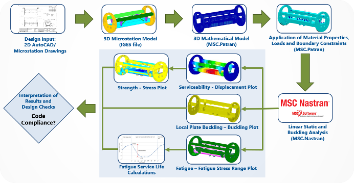
Typical FEA workflow

LEC retain MSC.FEA licenses for the following advanced structural analysis:

Solution Type Typical Application on LEC’s Projects
Linear static analysis / linear buckling analysis Independent design review and development of design solution for a variety of structures in the resource and heavy industrial sectors.
Natural frequency / modal analyses Dynamic sensitive structures (e.g., stacks/chimneys), preliminary analysis for structures subjected to vibrating loads (e.g., crushers).
Transient dynamic analysis
(frequency/time domain)
Detailed dynamic analysis for structures subjected to vibrating loads
Geometric and material non-linear analysis Structural forensic investigation.

LEC’s typical finite element analysis workflow is shown in the diagram below:

LEC-FEA-Workflow.jpg

Click here to explore some of the projects completed by LEC personnel using finite element analysis.